Charger Port, BMS configured & EV Driver Firmware modified
4th of March 2012
Many many small things where finished on the vehicle, most of it are so mundane that I will not include them in this report. The most exiting things where, 1. IEC 62196 Charger Port 2. BMS testing and configuration. 3. CAN-BUS marriage between BMS and Inverter can-bus.
Charge Port
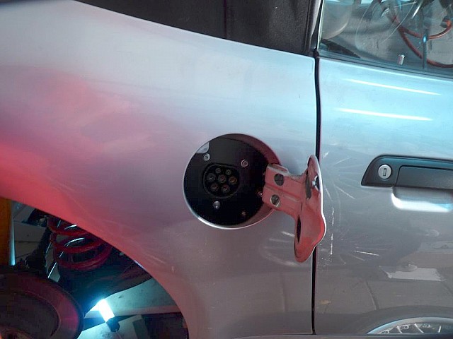
the Charge port has been installed recently. This required me to remove the (metal exterior) right rear body panel from the car. The removal of this panel which is a small project on its own, allowed me with my drilling 'skills' to drill holes that I ought to be required. The charge port IEC 62196 socket and connector I bought are made by "Do star" china, I acquired it from ecarconnectors.com
BMS Testing
After testing the BMS with re-charging the vehicle I noticed something strange in its SOC value. After a 'full' charge, the SOC would stick to the 'full' value until the cells would drop below the low voltage cut off points. This undesired behaviour was only present when I had both units daisy-chained in " Master & Slave " mode. An email was sent to seek for help on this matter. Ewert Energy (makers of the Orion BMS) provided quick tech support, even on Sunday! It all worked out perfectly with a firmware update. Thanks goes to Andrew!
CAN-BUS Marriage
Its still a young marriage, but the BMS and Inverter are now connected to eachother. This allows SOC, Amp discharge & regen limits to be notified without requiring separate wires for each signal. The BMS has a GUI to configure the CAN-BUS messages, the Inverter required little customization of the firmware. Tritium provides the EV-Driver Controls firmware for free upon request. This allows tailoring it to your vehicle.
BMS and Charger Installed
5th of January 2012
Good progress has been made with the charger and BMS setup. The Orion Battery Management System has been wired up to the Brusa charger and it has been tested for operation. The first (re)charge was fully attended, luckily I had the cells more than half full for this first test. Less than 2 hours passed until the BMS system commanded the charger to lower the charge current. It started the balancing phase of all the individual cells. Some cells hit the high voltage mark noticeably earlier than others. Ill hope to use the data from the BMS to find & replace the cells that are weaker (low capacity or higher resistance) than the average cell in the pack.
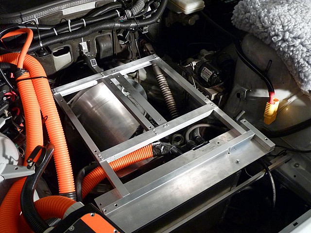
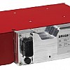
The charger and BMS needed a location somewhere in the vehicle. I chose the front side as there was still enough space above the motor. A bracket is fabricated that is only 'slightly' overkill in structural strength. The BMS resides in a splash proof electrical box. The lid of this box has been removed for the purpose of this picture.
BMS Testing
12 December
Time flies when you're having fun! Sadly little of the available time was spend on the z3. I did manage to find some time to finish the crimps on the rear BMS wire harness. Also I wrapped each group of wires in high strength and high temperature rated tape. To add a 2nd layer of defense I put the wires into a split corrugated tube. This should prevent the harness from externally induced damage .
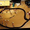
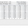
Also I tested the harness with the BMS module to see if it worked. A little moment of joy seeing all battery voltages being reported with no abnormalities.
All good:
Charger
2 December
For charging I have been struggling trying to make the decision on what to buy or build. At this moment there are no chargers available which can charge my battery pack (131 cells in series) other than the Brusa NLG5xx chargers. A moment of hope after finding the Sinexcel charger (19" quick charger of 12kw upto 700V) was lost again after hearing no response what so ever from my inquiries.
The only other option at this time is to build my own charger, but that may take a while also it would require a fair bit of testing and tweaking and perhaps a hardware revision to make it work as desired & compliant with european electronic emissions.
I don't want a project within a project. Since I only have two hands and one brain and limited time that I want to devote to the project.
Choosing a ready made charger makes sense. So it became the Brusa NLG513 with the air-cooled option.
BMS
2 December
Initial plan was to go without a BMS. But after some tests with the pack installed I noticed quite some divergence in capacity or self-discharge rate. This causes some cells to hit low earlier and when charging reach the high voltage cut off point much later. I want something to be able to find the weak-cells and filter them out. A BMS may be off help here. I chose for a decentralized BMS which allows split pack (front & back of the vehicle) configuration. Fast sample rate, high resolution, vast range of CAN bus customizations are possible. Also SOC Health can be calculated.
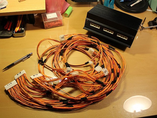
There's a downside to decentralized BMS'es compared to distributed, the wires! There are lots of them. Luckily its all rather simple and straight forward. I took my time to make the harnesses. Each crimp is made with care to ensure a high quality connection.
Here's the almost finished harness for the (104 series) cells in the back of the vehicle:
The front harness will be much less of a impressive set as those will be only for 27 series connections.
