Building Battery Boxes
Update 11 March 2012 There's a pattern developing where I should have updated the website earlier. Better late than never right?
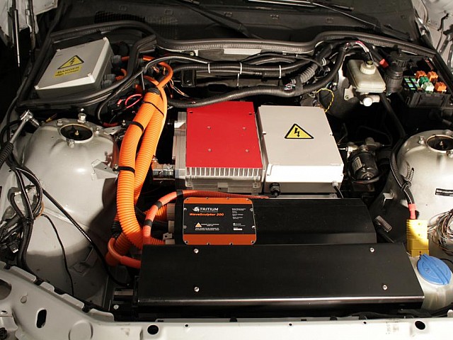
Front and rear battery boxes are ready now. I changed the design of the front battery box lid (I never showed the old design though..). Initially I choose aluminium, but this required heavy protection of the high voltage cables not to cause cuts / shorts. I choose poly carbonate as a solution. Its very strong, possibly strongre than the 2mm aluminium I was using, also it a very good electrical isolator.
The rear battery pack has also been given the poly carbonate treatment, which I left transparant for eye-candy pourposes ;)
Update 12 November
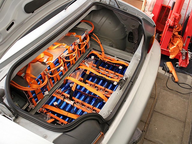
I should have updated this earlier, but the batteries are in! Well most of them are. A few more in the front still need to be connected.
The small battery box with the 8S3P are mounted snugly to the cargo space wall. I used 7 blind nuts, those should be enough to keep the batteries in place. Safety is important, this is always on my mind making parts or making cuts for or in the car. Because the small box is tilted, the batteries could fly-out in case of a small rear-end crash, I added 1 tonne restrains / safety belts for each pack to keep them where they are.
Also the big box is in now. All battery boxes are lined with 100um Mylar and using 0.5mm FR4 between the cell packs.
Update 7 August.
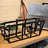
Battery box brackets and supports have been welded. Thanks goes to Peter, colleague from work for building & welding the brackets. The brackets are perfect!
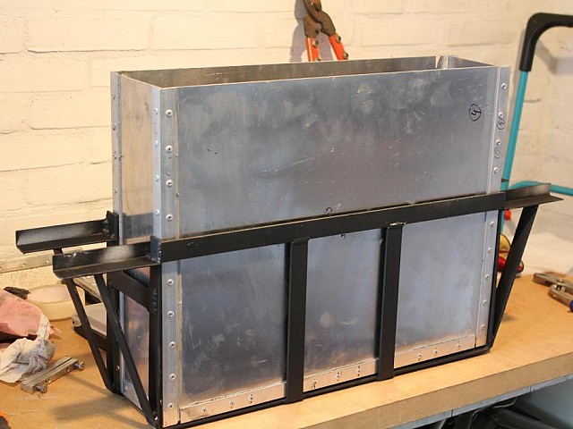
Box 1, holds 216 cells. It is mainly supported by the angle-iron, but a support brace has been added for extra strength.
Box 2 doesn't need brackets and is omitted in this line-up.
Box 3, space for90 cells maximum (which is likely to be loaded with only 81 cells to keep the voltage below 450VDC), is located behind the radiator. The box was too narrow to be mounted directly to the vehicle frame support bars. A bracket which supports the full weight of the box has been fabricated.
LifePo4 Pack grouping & Balancing
Balancing these LiFePo4 cells is mandatory before putting them in operation. I have chosen to go for top-balancing. Reason behind this is the fact that when the vehicle is charged, the vehicle is (often) left unattended. This has no influence on my decision to go for top-balancing directly, but what does is the fact that over-charging a cell is not entirely safe. If over-charged excessively it may vent due to electrolysis or overheat & vent. Over-charging a cell when the whole-pack is top-balanced is less likely than with any other method of balancing. A BMS, Battery Management system could help to protect the cells by telling the charger to throttle back on the charge-current. However a BMS for a 130 series pack will set me back between 1500 to 2200 euro's. It will prevent cell over-(dis)charging, can provide statistics of each cell voltage etc. But is that worth 2200 Euro's? In my un-experienced opinion with converting a car to an EV, I rather replace a few 'broken' cells throughout the years than spend the money now. It is blatantly a cost issue, if the BMS was cheap, Id really would have added it.
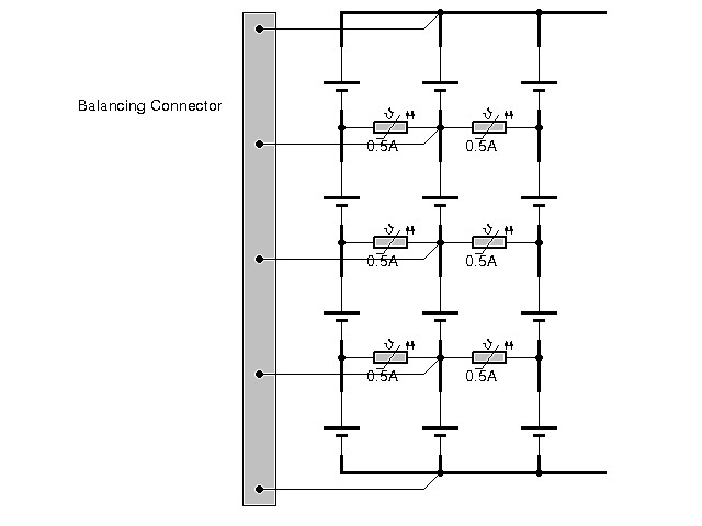
Balancing Connector
Am I scaring you with this decision to go without an BMS? Let's calm you down a bit. I decided to add a balancing port connector. This is an interface for an decentralized BMS. I will use this connector for monitoring groups of cells and montly/seasonly re-balancing the pack. This may take a while (full day perhaps) as the balancer will have to fix what has drifted in weeks/months.
Cell Protection Circuit
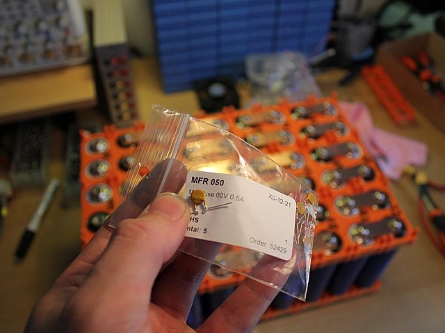
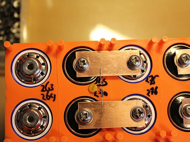
The pack configuration is 127S to 130Series, and 3 parallel cells. Placing three cells in parallel adds a risk in terms of fire safety. To tackle this issue, I decided to add a 0.5Ampere Multifuse. In a case of a massive cell failure (dead-short), the 2 other cells will not start feeding into the failed cell with high currents, which would only make matters worse. Instead, the multi-fuse becomes an High impedance path, trickling current to the dead-shorted cell.
Multifuse / PTC:
17th of July.
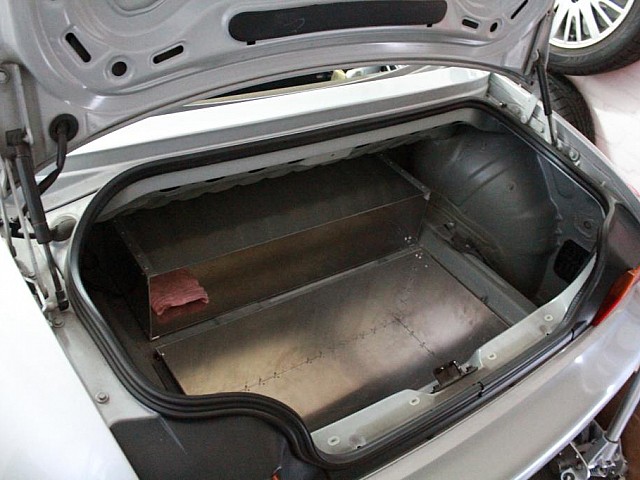
I decided to use Iron for the angle-profile to mount the trunk battery box to the car. Reason for this is mainly because it is stronger, also additional metal bands can be welded to it to provide additional support if needed.
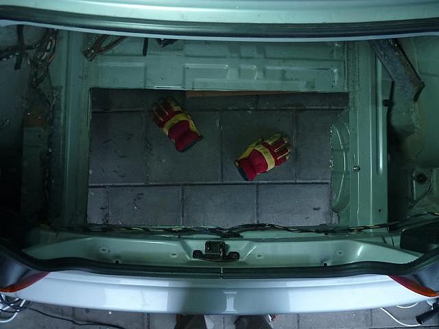
Also I've cut out the required space in the trunk floor:
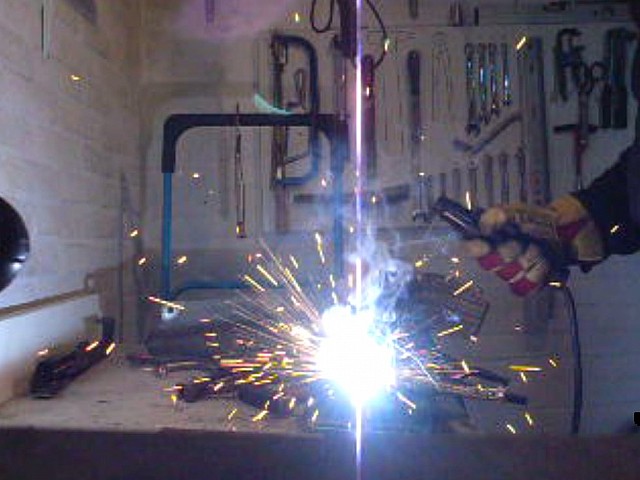
Also I took an attempt to learn shielded metal arc welding. (stick / electrode welding). Its not going to be something Ill master soon enough to be of use for my car project so ill have to ask someone else to do the required welding for me.
Battery Boxes
2nd July.
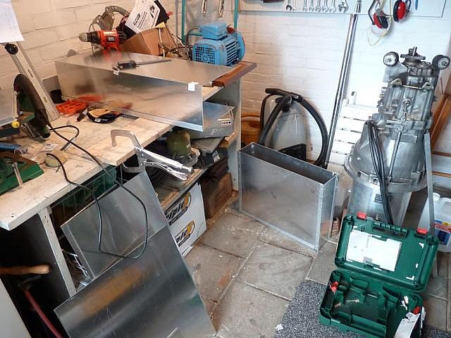
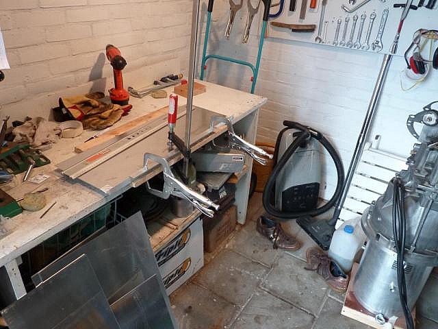
Today I started building the battery boxes. 2mm Aluminium sheet metal was cut to size which leaves me to drill the holes for the pop-rivets. At first 40mm distance between the pop rivets sounded like an easy plan, but after the first box I realized how many pop rivets I really need. The medium size box is assembled already, also it is test fitted in the engine bay. Fits with room to spare. Next assignment is the battery box for the smallest four 6x4 packs.
Batteries Arrived 29th of June.
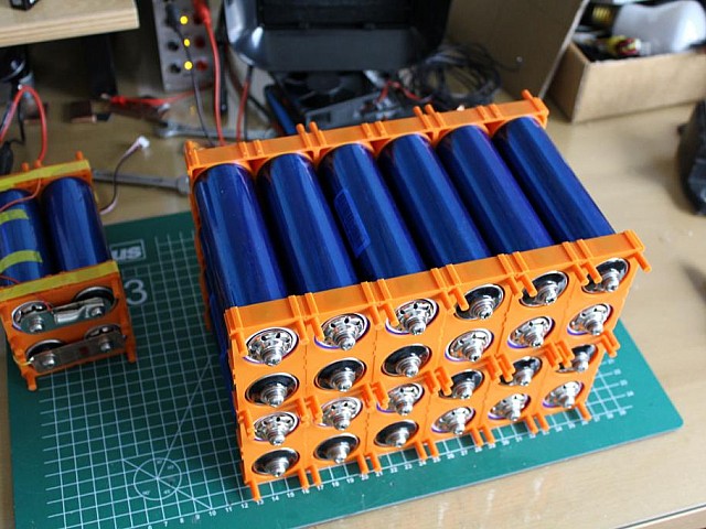
Hooray, the batteries have arrived. 22 Boxes, 420 cells of HW38140S. These are 3.2V 12Ah, 4 to 5mOhm cells with a 10C discharge rating. I will be making a 130S 3P battery pack from these cells. 130S means 130 in series , 3P means three in parallel. 130 in series produce a voltage of about 420V. I have calculated that the 130S3P configuration should enable me to draw 100kW from the battery. That is enough for this little car to make it move around swiftly.
This is the smallest configuration I made. Total of 11 packs will be assembled and put in aluminium boxes. The largest pack is 9x6 cells of which four will be made.The medium size pack is 9x3 of which only three are made. And the smallest is this 6x4 configuration of which four will be made.
Ive chosen to use 2mm Aluminium sheet metal as the enclosure material. Using pop-rivets and aluminium solder the boxes will be assembled to a rigid box like enclosure. Hopefully the fist box will be assembled this weekend.
