Temperature Gauge
The AC motor and inverter are water cooled. Keeping track of their temperatures is a nice feature but not absolutely required. The inverter has built in protection features for both the motor and it self. The dashboard has a temperature gauge already in place, removing it is likely going to require more time than keeping it as it is and putting some little effort into making it work.
With some additional firmware coding the inverter can report the temperature of the highest measurement source (motor or inveter, ext. input eg battery). Also digital outputs can signal the drive when the inverter is throttling down as part of its (self-)protection features to indicate that reduced power is available.
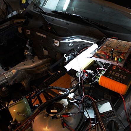
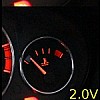
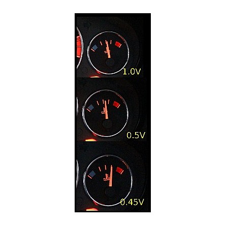
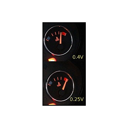
In order to be able to drive this nice temperature gauge some way of driving it must be derrived. A quick scan through the Electronic trouble shooting guides of the Z3 revealed about all the information required for temperature sensing. With a little further investigation I managed to obtain the following measurement results by using a 10kOhm potmeter and my old Fluke as the RPM generator. Oh almost forgot! The temperature sensor does NOT function without the RPM signal present. It must be one of these fance hidden features car makers put into their presentation layer of their firmware. Anyway, that was sorted and the tests finished swiftly.
Low Temperatures
Medium Temperatures
High Temperatures
X20 Connector again
I measured that the source voltage of the temperature pins of X20 pin 11 and pin 12 is 3.0V. The source impedance is 1363 ohm (short between pin 11 and pin 12 measures 2.2mA). Note that all voltages are measured between pin 11 and pin 12, not from chassis!
Using this data the following temperature & resistance value's can be derived :
| Volt | Ohm | Gauge |
|---|---|---|
| 2.50 | 6800 | BLUE |
| 2.00 | 2726 | BLUE |
| 1.50 | 1363 | 0.5 ticks |
| 1.00 | 681 | 2 ticks |
| 0.50 | 273 | 2 ticks+10% |
| 0.45 | 240 | 3 ticks |
| 0.40 | 209 | 3.5 ticks |
| 0.25 | 123 | RED |


